When you click on links to various merchants on this site and make a purchase, this can result in this site earning a commission. Affiliate programs and affiliations include, but are not limited to, the eBay Partner Network.
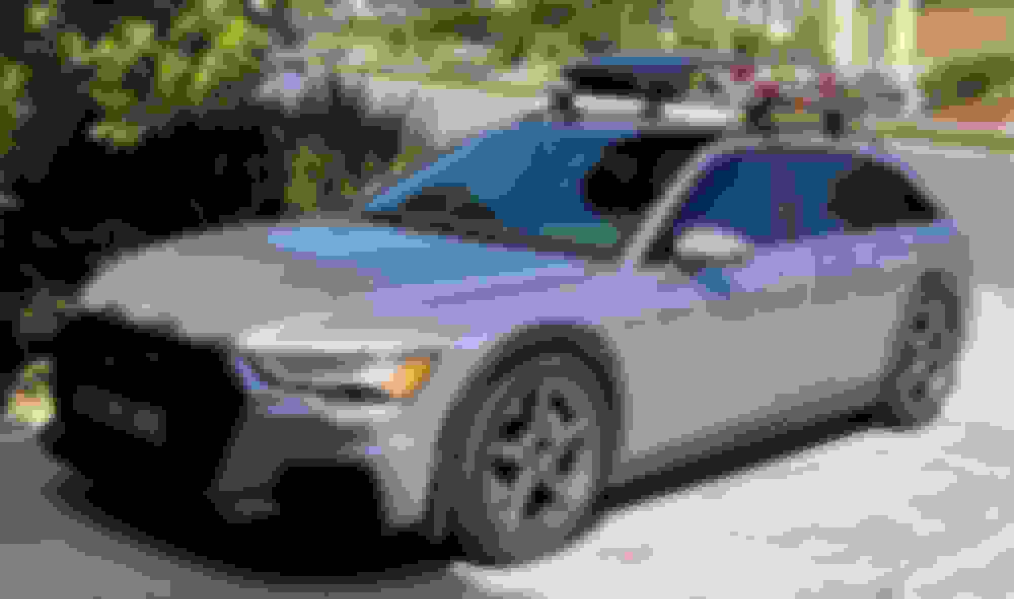
With several mods imminent I figured it was time to start a build thread for our A6 Allroad (C8). This will highly like be the last new car build I do thanks to my body doing its best to hasten me to the the end and a departure from this mortal coil (where does that phrase come from? I've never bothered to look it up). Getting this car was a bit of an odyssey and I've posted the story elsewhere (see link below). I was determined I would compromise this go round on the color and options. Super happy I found nearly exactly what I wanted:
2021 A6 Allroad Prestige
Florett Silver
Black interior with black headliner, rock grey stitching, Fine Grain Ash (this was the only thing that wasn't our first choice)
Black Optic (though surprisingly this package doesn't include black badges...HUH?)
Luxury Package
Executive Package
Side Assist
Options I skipped
Skipped Night Vision Assist (yeah, what am I going to do, turn of the lights and drive based on the MMI display of Virtual cockpit? Maybe it can see invisible aliens or something?
B&O 3D sound (I'm half deaf at this point so what's the point? Listen to podcasts and sports radio for the most part too)
A slew of coding changes too numerous to list. Used information over on the OBDEleven forum
Label free sun visors
Radar detector hardwire
Cup holder swap to version with a lid. Will post my experience competing this. In the big picture, this was fairly easy though it did involve removal of a few pieces
Dynamic turn signal (this one frustrates me and I've posted my thoughts and experience elsewhere (will link to those threads at some point. Giving the OSRAM units another try.)
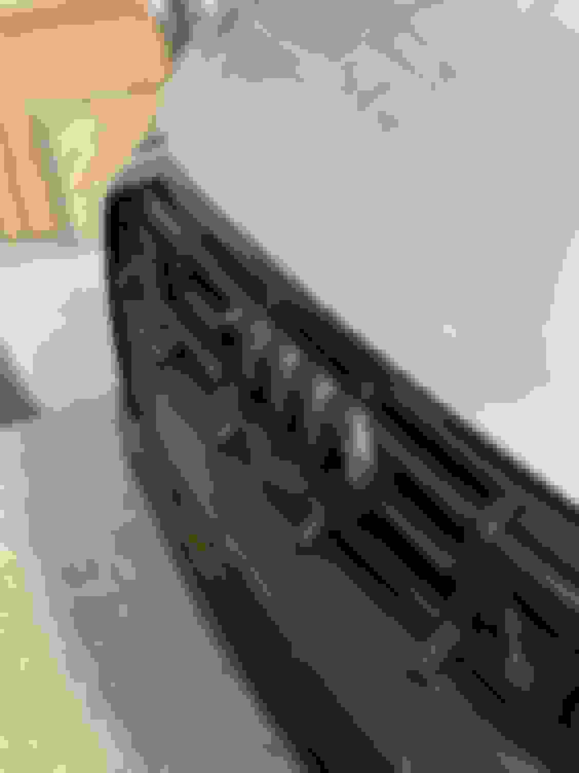
ABT AEC - installed myself after sorting out where to mount the AEC (spoiler alert, it goes behind the front left wheel liner nearest the driver - see the post below on the install).
CETE ASC set at 1” / 25mm - installed by TAG Motorsports
Black emblem swap - posted my search for black badges over on Audizine. Still looking for a front Quattro grill badge, however. Nearly done with only the A6 badge outstanding (other than the aforementioned Quattro grill badge).
Auto Stop/Start has been defeated and I rejoice! See below for a description of the install
Installed a BMC air filter to replace the OEM air filter
Added cargo area rail system
BC Forged HCS35 20x9.5, et 35 wheels in gloss gunmetal w/Continental ExtremeContact DWS 06 Plus 275/40/20 tires
Upgraded to OEM sway bars
Installed Euro tail lights w/rear fog lights - took the shop ~7 hours to complete!
Flat bottom steering wheel (see below for the fun I had installing)
Installed Audi Splash Guards
Changes and mods coming in next 1-2 months:
Nothing right now, though that may change when I talk my self into Euro head lights…
Changes to be tackled sometime in the future:
Possibly asymmetric side mirrors
Full light upgrade to add the Euro Matrix headlights, though don't think these are even available yet. Got to get rid of the ugly orange side markers, pick up the properly sweeping turn signals. Not to mention the better beam pattern and hopefully improved automatic high beams
Changes I'm not sure of but maybe...
FMIC - haven't really looked into what, if anything, is available. Wouldn't surprise me if there's nothing. That said, A6 mods might fit so...
Final photos of the cup hold swap. I chose to try an aluminum lid rather than a wood trim. This is because the grain of the wood wouldn't match the grain of the existing trim in the car. I kind of like the contrast...you be the judge.
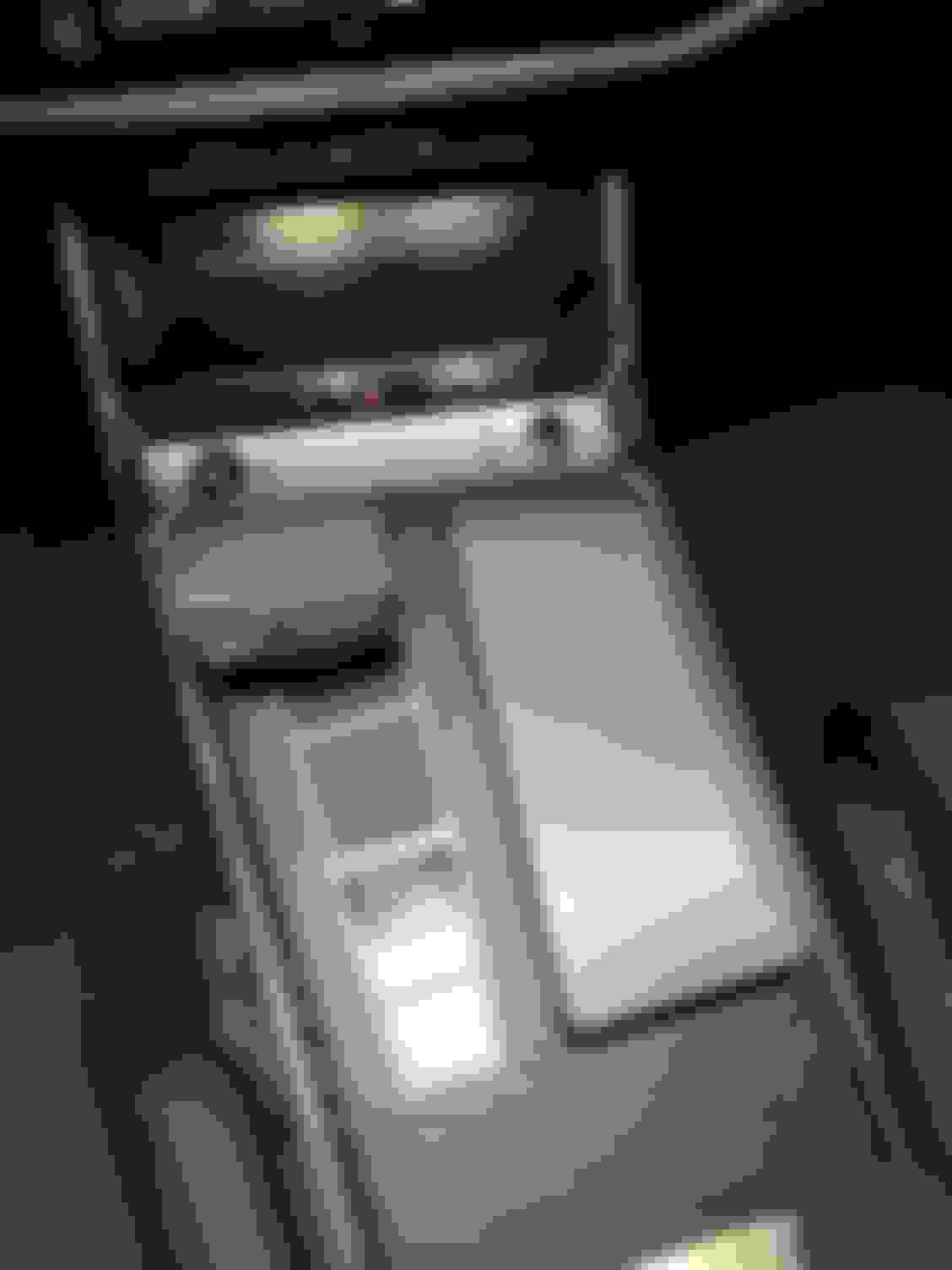
Installed the ABT AEC Power Upgrade yesterday. In the grand scheme of things, this was a relatively easy installation. The install instructions provided by ABT are some of the more complete I've come across. That said, there are a few gaps. Like a good little DIYer, I read through the instructions first before starting anything. Good thing I did, as it immediately because apparent that the location where the AEC is to be mounted isn't described. Each step of the install process is accompanied by a photo of the end product that results from the step. These photos are quite helpful, however, the one of the AEC does not provide enough detail to see where it goes. I emailed ABT to get clarification as well as putting up posts on the forums. ABT replied overnight, stating the AEC is mounted behind the the front, driver's side wheel well liner. However, they did not say if it went behind the front of the wheel liner or back side, closer to the driver. So I took both off and determined that the AEC installs closer to the driver. Once I sorted that out I felt comfortable starting the installation.
As I mentioned, each step of the install is accompanied by a photo showing the intended configuration. I printed the instructions out, but found that the photos were too small in some cases to make out what exactly the end product should look like. I remedied this by using my iPad and zooming in on each photo. This worked by everything right up to the step to connect the power lines. it's at this point the instructions do not provide enough detail. Specifically, where to route the power lines across the engine bay. The Allroad's ECU is on the driver's side, while the power connections are on the opposite side. Connecting to power is the last step prior to connecting and mounting the AEC. At this point, I was was committed to finishing. I ended up routing the wires under the Lock Carrier Cover (BTW, where did this name come for this part? It covers the radiator area. I've always wondered...) and under the intake scoop, then across to the power terminals.
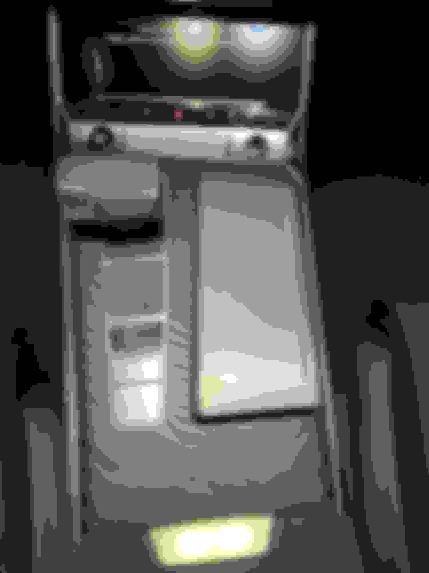
The final step per the instructions is to attach the AEC to the mounting bracket, attach the cables coming from the mounting harness to the AEC, then mount the AEC/bracket to the car. Well, I found there were several "missing" steps needed to complete this step. None of which are described. The wiring needs to be routed into the space behind the wheel well liner. The need to do this is mentioned in the instructions, but there is no mention of where to run the cables or where to find the "gaps" in the sheet metal through which to run the the connector and wire. Again, I was committed at this point so couldn't wait for email responses to my questions. I "solved" this as follows:
Cable routing: I ended up pulling out two trim pieces that run along the outer edge of the engine bay and running the cables behind them.
Access to wheel well: there is only one possible gap large enough through which to run the connector into the wheel well located behind behind a piece the of foam stuffed into the space behind the trim piece I'd removed that was closest to the windshield
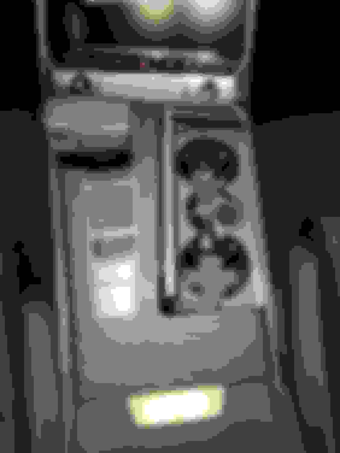
Next came connecting the wiring harness to the AEC. Well, the the connector is actually made up of two pieces, the one attached to the wiring harness, and a second that is not. It's kind of obvious both halves need to be attached to the AEC, but the instructions don't really mention this in much detail. Then the bracket is attached to the car. There is a photo of this in the instructions.
At this point everything is connected and the wiring should all be in place. All that was left was to do some final "clean up" of the wiring harness. This turned out to be more of a challenge than expected. Essentially, determining where to route the wiring from the ECU area to where the cable was routed to the trim area was not obvious. Nothing is mentioned in the instructions. After several trial and error attempts, I finally found something I liked.
Put everything back together, put the wheel back on, ran a scan for errors (there were none), the took a short test drive. Our car is still in the break in period (only ~120 miles on the odometer) so I couldn't really get on it to test things out. Throttle response did seem to be improved, something I was hoping for. I had intended to take lots of pictures to post, but ended up taking none, sorry.
Anyone thinking of choosing this system so that it can be removed prior to taking the car to the dealer may want to think again. It is not an easy removal.
BTW what's the CETE Suspension Control do? let you adjust the min/max height by adjusting sensor arm?
Gives greater control of the air suspension. Can lower the car without making physical changes to the suspension. There is a show mode that slams the car (I'm not all that interested in that, but other are). The car can be "forced" into the lowest setting at any speed. Stock, the lowest setting can't be achieved until the car reaches a specified speed. I think I saw on another thread that the car can be lowered up to 30mm (or maybe it was 20mm) max for driving. I like the aesthetics of a moderately lowered car and don't need it to left up when I've parked. Settings are made via a phone app. This will be the first app controlled suspension I've had, so its all new to me.
BTW what's the CETE Suspension Control do? let you adjust the min/max height by adjusting sensor arm?
It basically intersects the sensor readings going to the computer and tricks it. The settings are also tied to drive mode so you can set different height adjustments for different drive modes. I will say the cete doesnt recognize Allroad mode. Hopefully they will update their software to include the allroad specific drive modes.
CETE ASC installed. Elected to lower the car 25mm when in Dynamic and Individual (suspension set to dynamic) and leave the rest alone. Picking up the car later tonight and will post impressions and pics either tonight or tomorrow.
Replaced nearly all the badges with glossy black. A6 badge is pending the black one arriving soon. Pics of what�s been done so far below:
Auto Start / Stop has been defeated! I purchased a Memory Module from a seller on eBay located in Australia. Took ~3 weeks to arrive thanks to COVID. Install instructions were emailed directly. The install in a C8 is very straightforward. However, I ran into two minor snags anyway:
The Can Bus unit where the wiring changes are made was not where the instructions said it would be. Instructions said "behind the driver seat". Nope, no such thing. After an overnight email exchange, this was solved - the Can Bus is under the rear bench seat.
Issue two, one of the four wires required to be moved from the 54 pin connector was wrong. Another email exchange, and all is good.
Install is relatively easy, albeit awkward given the location of the Can Bus 54 pin connector to be re-wired. Steps:
Remove rear bench seat per erWin guide (attached)
Remove child restraint plastic inserts (this requires removing the caps, then
Pull up on front of bench seat with force
Depending on options, the rear bench seat may have electrical connectors. Disconnect is optional as Can Bus can be accessed by propping bench seat up.
Can Bus is located in middle of car under the rear bench seat. There was only one on my car, hard to miss. Remove two nuts to release. I elected no to disconnect the electrical connectors and completely removed the bench seat (because I'm stupid). I flipped the bench seat up and rested it against the rear seat back rest. This meant I had to work around the bench seat because it was partially in the way. As I said, dumb, but I'm stubborn.
Remove black plug from memory module wiring harness - this is where the four wires removed from the 54 pin connector will be attached
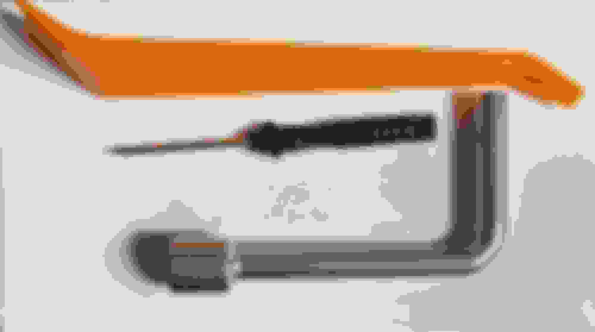
Locate requisite wires per corrected instructions (in my case, the instructions were wrong for one of the wires - instructions said to move red wire from location 17, this was wrong. Correct wire is located in position 18 - see photo)
Remove wires and install in the corresponding black plug attached to Memory Module
Install four wires from memory module into 54 pin connector where other wires were removed
 07-01-2021, 06:30 AM