AAN Positive Crankcase Ventilation (PCV) System with revised diagram, PNs and Links
 03-21-2011, 01:21 PM
#1
AudiWorld Super User

Thread Starter
Like all internal combustion engines, the 20vt (3B, AAN, ABY and ADU) engine crankcase and the area under the cam cover creates oil vapours due to the heat in the engine and in the oil. In addition, because the piston rings do not seal 100%, there is some blow-by of air-fuel mixture that ends up in the crankcase. Neither the oil vapours or the blow-by can be allowed to build up and leak uncontrolled to the atmosphere (in the "old days", e.g. before around 1962, they did vent to atmosphere, as a combined "blow-by", an oil vapour/smoke). In addition, if the vapours were allowed to build up, they would pressurize the oil system and push oil past the crank seals, etc.
The 20vt engines have a system that draws these vapours into the intake manifold. When the engine is under vacuum, i.e. idling or low load driving, these vapours are drawn through a one way ("bleeder") valve into the intake manifold, just underneath the throttle body. This valve is a ball check valve, i.e. it allows flow on way but no the other. When the engine is under vacuum, the ball is lifted off the valve seat, allowing flow of crankcase and cam cover vapours to flow into the intake manifold.
Here is the bleeder valve (aka "one way" or "non-return" valve), as shown in the Arizona Autohauz on-line catalogue:

However, when the engine is under boost, you don't want to pressurize either the camcover or the crankcase with boost pressure (because it would definitely push oil past the crank seals or out the cam cover cap). As a result, the one-way valve (ball-type check valve) closes. At that point, the pressure control valve that was previously held shut by its internal spring pushing its diaphragn against an orifice opens under the vacuum caused by air going past the connection to the turbo to intercooler hose, drawing vapours into the intake hoses (all downstream of the MAF). As a result, the crankcase oil vapours still get to the intake manifold, just through a different pathway.
Here is the pressure control(regulating) valve from the ECS tuning website:
.jpg)
The crankcase ventilation system on the 20Vt (e.g. AAN) is operated mechanically and is not controlled by the ECU. The only connection (so to speak) is the ECU controls boost (and vacuum) depending on the throtttle position and the crankcase ventilation system function changes with boost/vacuum it sees.
Under boost, the oil vapour-laden crankcase air goes to the MAF to turbo hose; under vacuum it goes to the intake manifold.
Suffice it to say, if there is a rip in one of those hoses or the PCV (non-return) check valves is stuck open, you can have problems.
Personnally, I replaced both valves when I did my first FMIC.
The Pressure Control Valve in the above diagram is called a "pressure regulating valve" has a 034129101A part no. (Note: 101A has been superceded to 101B and apparently its less expensive). The bleeder valve, aka "non-return valve" is a ball-type check valve. Because it is a one-way ball-type check valve, it needs to be installed in the correct orientation. PN is 035103245A.
Note the orientation of the bleeder valve ("nipple" up, wide part (the ball cage and seat, down).
There is also something called a "flame deflector plate" ((Ref: Item 5, in the above labeled diagram(PN 035 103 477A) located just downstream (towards the engine) from the pressure regulating valve. This thing is supposed to stop flames travelling in these hoses - might just be a means of condensing oil vapours - no idea. Here is a photo:
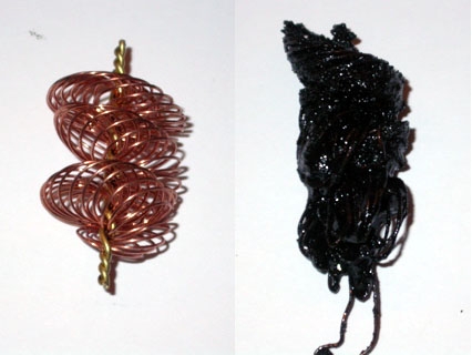
Photo courtesy of Jamo on the S2 forum.
It's supposed to look like the clean one on the left, not like the one on the right.
If there is an issue with the pressure control valve stuck open, then oil vapours will be drawn into the turbo to intercooler hose all the time. This will result in build up of condensed oil vapours in the intercooler and/or the Michelin Man hose. Oil in the intercooler will decrease the heat transfer efficiency and oil in the MM hose will cause it to rot and split.
If the system components, e.g. flame arrestor, become clogged downstream of the pressure control valve or the pressure control valve fails closed, and the PCV valve works properly, the will no way for the crankcase vapours to go anywhere, except back-flowing through the cam cover vent at the back of the head and out the oil cap on the cam cover. This is not a good thing.
HTH
The 20vt engines have a system that draws these vapours into the intake manifold. When the engine is under vacuum, i.e. idling or low load driving, these vapours are drawn through a one way ("bleeder") valve into the intake manifold, just underneath the throttle body. This valve is a ball check valve, i.e. it allows flow on way but no the other. When the engine is under vacuum, the ball is lifted off the valve seat, allowing flow of crankcase and cam cover vapours to flow into the intake manifold.
Here is the bleeder valve (aka "one way" or "non-return" valve), as shown in the Arizona Autohauz on-line catalogue:
However, when the engine is under boost, you don't want to pressurize either the camcover or the crankcase with boost pressure (because it would definitely push oil past the crank seals or out the cam cover cap). As a result, the one-way valve (ball-type check valve) closes. At that point, the pressure control valve that was previously held shut by its internal spring pushing its diaphragn against an orifice opens under the vacuum caused by air going past the connection to the turbo to intercooler hose, drawing vapours into the intake hoses (all downstream of the MAF). As a result, the crankcase oil vapours still get to the intake manifold, just through a different pathway.
Here is the pressure control(regulating) valve from the ECS tuning website:
The crankcase ventilation system on the 20Vt (e.g. AAN) is operated mechanically and is not controlled by the ECU. The only connection (so to speak) is the ECU controls boost (and vacuum) depending on the throtttle position and the crankcase ventilation system function changes with boost/vacuum it sees.
Under boost, the oil vapour-laden crankcase air goes to the MAF to turbo hose; under vacuum it goes to the intake manifold.
Suffice it to say, if there is a rip in one of those hoses or the PCV (non-return) check valves is stuck open, you can have problems.
Personnally, I replaced both valves when I did my first FMIC.
The Pressure Control Valve in the above diagram is called a "pressure regulating valve" has a 034129101A part no. (Note: 101A has been superceded to 101B and apparently its less expensive). The bleeder valve, aka "non-return valve" is a ball-type check valve. Because it is a one-way ball-type check valve, it needs to be installed in the correct orientation. PN is 035103245A.
Note the orientation of the bleeder valve ("nipple" up, wide part (the ball cage and seat, down).
There is also something called a "flame deflector plate" ((Ref: Item 5, in the above labeled diagram(PN 035 103 477A) located just downstream (towards the engine) from the pressure regulating valve. This thing is supposed to stop flames travelling in these hoses - might just be a means of condensing oil vapours - no idea. Here is a photo:
Photo courtesy of Jamo on the S2 forum.
It's supposed to look like the clean one on the left, not like the one on the right.
If there is an issue with the pressure control valve stuck open, then oil vapours will be drawn into the turbo to intercooler hose all the time. This will result in build up of condensed oil vapours in the intercooler and/or the Michelin Man hose. Oil in the intercooler will decrease the heat transfer efficiency and oil in the MM hose will cause it to rot and split.
If the system components, e.g. flame arrestor, become clogged downstream of the pressure control valve or the pressure control valve fails closed, and the PCV valve works properly, the will no way for the crankcase vapours to go anywhere, except back-flowing through the cam cover vent at the back of the head and out the oil cap on the cam cover. This is not a good thing.
HTH
Last edited by UrS4boy; 07-13-2011 at 09:49 PM.
 03-25-2011, 09:04 AM
#2
AudiWorld Super User
Thread Starter
The ABY and ADU PDV system is similar but different than the AAN because of the intake manifold differences. Same PNs for the bleeder valve and the Pressure regulating/control valve.
Last edited by UrS4boy; 07-13-2011 at 09:55 PM.

Thread
Thread Starter
Forum
Replies
Last Post
cranberryjello
Audi A5 / S5 / RS5 Coupe & Cabrio (B8)
1
09-27-2010 07:52 AM
Just Paul
Audi 90 / 80 / Coupe quattro / Cabriolet
3
11-01-2007 10:38 AM
moribundman
12v V6 Discussion
6
05-21-2003 07:50 PM