Audi A6 C6: How to Replace Ball Joints/Control Arms
Audi uses a complex system of four control arms to create a phantom pivot point, which allows its cars to steer so well. The bushings and ball joints on these arms need to be replaced periodically if you want to keep that razor sharp handling.
This article applies to the Audi A6 (2005-2016)
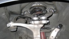
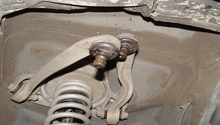
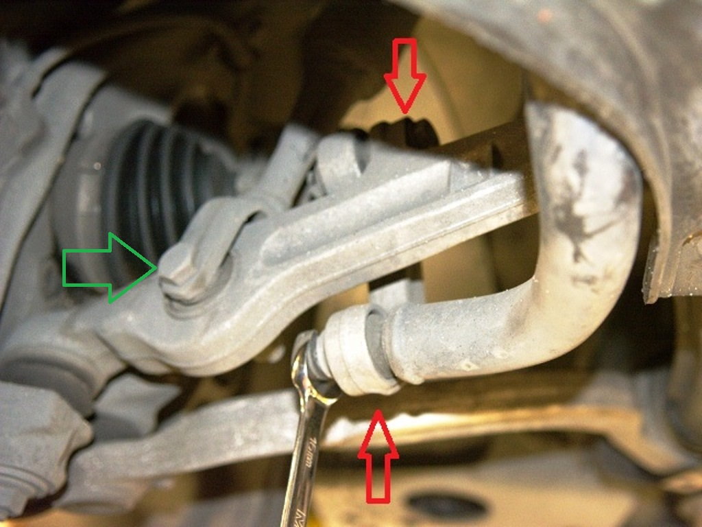
The control arms are critical components that make up a large part of your vehicle's front suspension, and the ball joints and bushings are part of them. If these components are damaged or worn (similar to an athlete suffering an injury to their ankle), your vehicle's ride and handling will be compromised. Like many other components, Audi control arms are considered "wear and tear" items and should be serviced regularly. From a visual stand point, the "rubber" portion of the bushings and ball joints can show signs of cracking or tearing, which is a precursor to them failing completely. Here's how to replace the ball joints/control arms in the Audi A6.
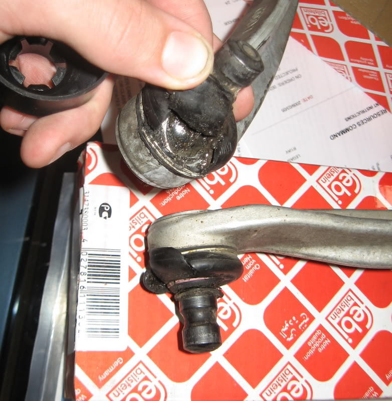
Figure 1. Torn ball joint boots shown.
Materials Needed
- 16 millimeter socket and ratchet
- 16 millimeter box end wrench
- Two jack stands
- Jack
- Ball joint fork
- Pry bar
- Hammer
- Long drift
- Air wrench if available
- WD-40
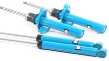
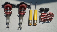
- Replacement suspension components
Step 1 – Raise vehicle and remove wheels
The vehicle will need to be raised on level ground to service these components. Jack the car up and place a jack stand under each side. If you are doing just the front end, there is no need to raise the rear, but it may be easier to work under the car with it raised at all four corners.
The wheels need to be removed to access the control arms and ball joint assemblies. Remove the wheel with the supplied tools in the Audi tool kit, an impact gun or a socket and breaker bar.
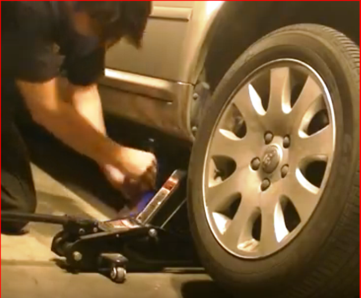
Figure 1. Jack up the A6 and secure it on jack stands. 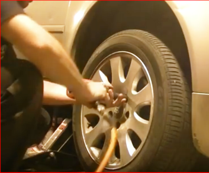
Figure 2. Remove wheels with an impact gun.
Pro Tip
If you don't have an air or impact gun, it is wise to loosen the bolts to the wheels while the car is still on the ground.
Step 2 – Remove pinch bolt
With the wheels removed, you can see the entire control arm assembly. There is a single pinch bolt holding the ball joints to the steering knuckle.
- Remove the nut from the upper control arm bolt with a 16 millimeter box wrench and socket.
- Once the nut is removed use a soft mallet to tap out the pinch bolt.
- The ball joints should be easily removed now; if needed, a flat blade screwdriver can be inserted to help get it loose.

Pro Tip
The pinch bolt may be seized in the pinch clamp and not budge. A block of wood can be used when tapping the bolt so as to not damage the threads. You can also spray soak the bolt in WD-40 ahead of time.
Step 3 – Remove lower bolts
In order to remove the control arms easier, you need to drop the entire shock assembly down from its tower, which requires disconnecting the lower mount. Also, in order to remove the lower control arms, you are going to need to disconnect the sway bar end link.
- Use impact wrench or breaker bar with a box wrench on opposite end to work the lower shock bolt out.
- The sway bar end link should come off fairly easily with a ratchet or box wrench.
Pro Tip
Spraying WD-40 or PB blaster ahead of time on these bolts will aid in removal.
Step 4 – Locate upper strut bolts
Now that the bottom portion is free, the upper part of the assembly will need to be freed as well.
- Open the hood and remove the plastic cover back by the windshield.
- On the driver side you may need to remove the coolant reservoir to get to the bolts.
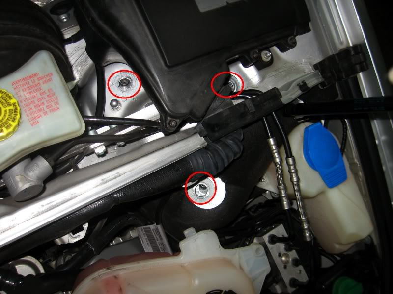
- Locate the bolts on each side that hold the upper mount to the chassis.
- Use impact wrench or socket wrench to remove bolts.
Pro Tip
There may be plastic grommets covering the bolts, and on the driver side you may have to remove some other components to reach them.
Step 5 – Remove old components
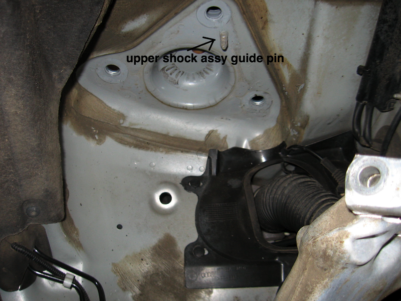
Now that the assembly is free from the vehicle, you can reach the upper control arm mounting bolts back by the shock.
- Pull the assembly out and away from the fender well.
- Place on a clean surface or workbench.
- Remove the 16 mm bolt and nut holding the control arm.
- Separate control arms from strut housing.
- Repeat for both sides.
Pro Tip
You can use an impact wrench on the opposite side of a box wrench. If the bolts are really stubborn, you can soak them in WD-40 first.
Step 6 – Install new control arms
Once you have separated the old control arms from the housing, the new ones can be installed by doing the same steps in reverse.
- Line up the new control arm end with the bolt hole.
- Guide bolt through and swing arm to the rest position.
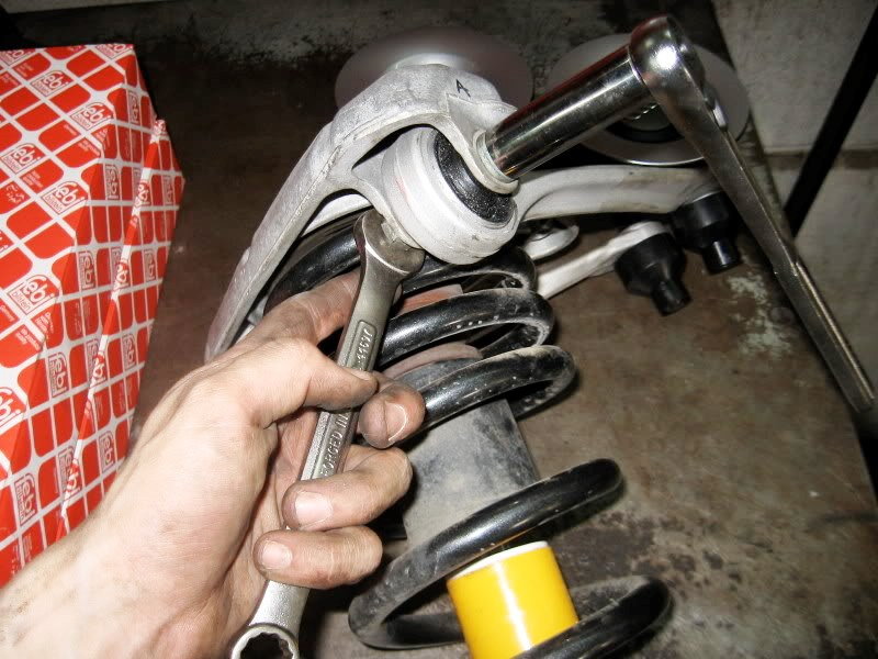
- Use gear wrench and open ended wrench to tighten the position of the arm with the bolt.
- Repeat for second arm assembly.

Pro Tip
When you install the new control arms onto the housing, don't tighten them fully. Once the assembly is in the vehicle, place the jack under the steering knuckle and jack until most of the weight is on the suspension again. Then, tighten the bolts fully.
Step 7 – Remove/replace lower control arms
The lower control arms are easier to access but a little more difficult to remove.
- Remove the lower ball joint nuts.
- Use a ball joint separator or pickle fork to separate ball joints from control arms and steering knuckles.
- Remove control arm bolt on the other end and it will drop free.
- Installation is the reverse.

Step 8 – Reinstall assembly
Once the new control arms are secured to the strut assembly, it can be installed back on the vehicle.
- Guide the assembly under the fender well.
- Tighten upper strut bolts back in the engine bay.
- Align lower shock fork and reinstall lower bolt.
- Reinstall pinch bolt on the upper control arms.
- Tighten the bolts for the upper control arms to spec.
Related Sites and Video
- Audi A6 Upper Control Arm Replacement - YouTube
- DIY Upper Control Arms - AudiZine.com
- Front Control Arm Replacement - AudiZine.com
- How to replace Upper Control Arms - Blauparts.com